
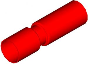
Reducing/Expanding
Expansio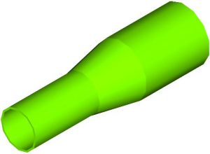 n or reduction of the tube diameter is frequently employed to maintain a good balance between strength and length of a component.
Transitions are smooth and free of the interference that results from the use of adapter and coupling devices. Generally, the wall thickness of the small diameter section will be slightly heavier than the larger diameter.
To avoid added operations, the ratio of the Small O.D. / Large O.D. should be .7 or greater. However, by using multiple operations, the ratio can be exceeded.
| Feature | Limits | Tol. (in.) | |
|---|---|---|---|
| Reduced Length | -- | ±.010 |  |
| Transition Angle | 11' to 15' | -- | |
| Overall Length | -- | ±.010 |
Bending
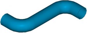
The possible configurations of bent tubes are virtually unlimited. From the manufacturing point of view, the greater the bend radius to O.D. relationship becomes, the easier it is to produce a component with minimum distortion (ovality) in the bend area. This is also true relative to wall thickness, in that the heavier wall products generally bend better.
| Feature | Limits | Tol. (in.) | |
|---|---|---|---|
| Bend Radius | 2 x O.D. (ref. min.) | ±.05 R |  |
| Distance "L" | 2 x O.D. (min.) | ±.005 | |
| Bend Angle | -- | ±1 deg. | |
| Straight Length | -- | ±.010 |
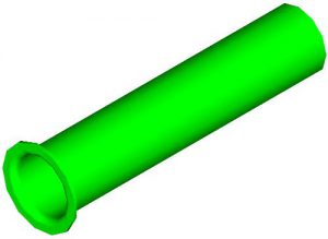
Rolling Groove
One or more grooves may be employed to increase turbulence of a fluid passing through the tube, thereby improving thermal transfer. The groove may also be used to locate other components inside the tube or provide a means for retention of subsequent assemblies. Due to work hardening in the groove area, ductile materials and tempers should be specified.
| Feature | Limits | Tol. (in.) | |
|---|---|---|---|
| O.D. | 187" max | std. |  |
| Wall | 5% to 15% O.D. | std. | |
| Groove Width | None | -- | |
| Groove Depth | .15 x O.D. (max) | -- | |
| Groove Location | 7 x O.D. (min) | -- |
Beading
Beading can serve to provide a seat or stop on the outside of the tubular component. If the bead diameter is only slightly larger than the original tube diameter, a friction fit can be developed between the bead and the mating part. Since the bead is essentially free form, the shape is not easily controlled.
Subsequent to beading, thermal treatment may be required to relieve stresses and improve mechanical integrity.
| Feature | Limits | Tol. (in.) | |
|---|---|---|---|
| Bead dia. (max) | 1.4 x O.D. | ±.002 |  |
| Bead location | .050" (min.) | ±.003 | |
| Bead width | 2 x wall (min.) | ±.003 | |
| Overall length | -- | ±.003 |
Flaring
Flared ends are commonly used as sealing surfaces; 37° flares, also known as AN fittings, required a backup sleeve and are normally used in high pressure applications.
45° flares, also known as SAE fittings, are commonly used throughout the automotive industry.
90° flares, also known as TRI-CLAPMS fittings, require a gasket and are widely used in sanitary applications where ease of disassembly is required for regular cleaning operations.
| Feature | Limits | Tol. (in.) | |
|---|---|---|---|
| Flare diameter | 1.4 x O.D. | ±.004 |  |
| Radius under head | .050" (min.) | ±.002 | |
| Transition Radius | under head rad. +wall | -- | |
| Overall length | -- | ±.003 |
Notching
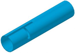 Notches in the tube wall may allow internal components to be viewed directly for positioning or assembly operations.
If the notch width exceeds I.D. minus 4 x wall thickness, the notching tool action must be tangential, rather than radial, to keep distortion of the tube to a minimum.
In parts under 2″ in length, Notching can be combined with tube cutting, for cost savings.
| Feature | Limits | Tol. (in.) | |
|---|---|---|---|
| Location | 2 x wall (min.) | ±.003 |  |
| Notch length | 2 x wall or .010" (min.) | ±.001 | |
| Notch width (min.) | 2 x wall or .010" (min.) | ±.002 | |
| Notch burrs | 0-0.002" (max.) | -- |
Lancing
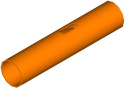
The Lanced tab is appropriate as a stop for I.D. assemblies or to create friction between mating parts. Since creation of the tab feature does not generate any chips, it is one of the easier fabrications to produce.
| Feature | Limits | Tol. (in.) | |
|---|---|---|---|
| Location | 2 x wall (min.) | ±.003 |  |
| Tab width (min.) | 2 x wall or .010" | ±.001 | |
| Tab width (max) | I.D. minus 4 x wall | ±.001 | |
| Tab length (min) | 3 x wall | ±.010 | |
| Tab clearance | -- | ±.003 | |
| Window burr | -- | 0-0.002 |